Solidworks Flow Simulation
Solidworks Flow Simulation- is an intuitive Computational Fluid Dynamics (CFD) solution embedded within SOLIDWORKS 3D CAD that enables us to quickly and easily simulate liquid and gas flow through and around our designs to calculate product performance and capabilities.
What is simulation ?
Simulation is simply how a product or a part behaves under some fixed condition for ex if i push a square block with some force how the block behaves or changes its dimension (minimal) under that force, or suppose the door of your room is blocked and you are trying to open it by pushing it so how the door is going to behave and how much force you need to apply to open that one is given by simulation.
Simulation is also used when the real system cannot be engaged, because it may not be accessible, or it may be dangerous or unacceptable to engage, or it is being designed but not yet built, or it may simply not exist. ex you have to design a car for your customers ,you can't just start manufacturing it by welding ,joining ,cutting .You have to make a prototype (model) on cad softwares ,analyse its working ,test it on different parameter and after you are all done with your model then start manufacturing.
In flow simulation we analyze the flow of fluids over a body or from inside/through a body .Its application are designing of airplane, cars,vents, heat transfer and many more. It can be used in many industries including aerospace, power generation, oil & gas power conversion, transportation, additive manufacturing, automotive, and others. CFD capabilities cover a wide range of application within these industries including turbomachinery rotating cavity systems, secondary flow & engine sealing, combustor cooling, fuel/lube systems, and power plant piping networks. it can also be used for renewable wind turbines and electrical generator cooling and thermal management. For additive manufacturing, it allows for heat exchanger design and optimization.
SOLIDWORKS Flow Simulation is a general parametric flow simulation tool that uses the Finite Volume Method (FVM) to calculate product performance through “what if” studies that allow you to perform optimization using the results.
I remember the first time i completed flow simulation on a body . I was in a state of euphoria and got engulped with vows and i was thinking how i was able to make a masterpiece.
Step 1:
Make your part/component over which analysis is needed and save it. I created a hollow U tube .Add flow simulation add ins from the options in menu bar. If it is already there in your command manager then you can proceed to step 2.
Step 2 b:
In the below shown window choose your unit system .Prefer SI unit system and in tab below to this it will show you unit of various quantities in that unit system . After you are done click next.
Step 2 c:
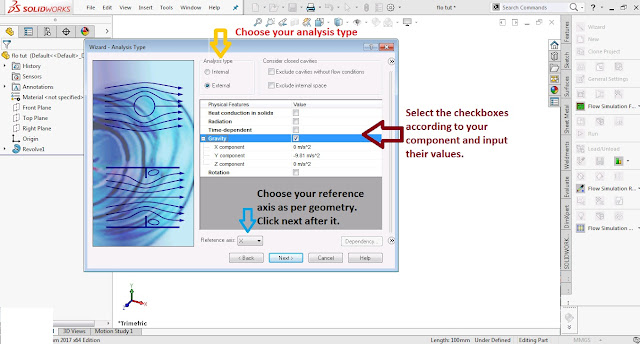
In next window you have to choose type of analysis.
For my present body i used External analysis.
In physical features menu there are
Step 2 d:
Choose the type of fluid for your CFD/Flow analysis .There are hundreds of fluid available here. From newtonian to ideal ,from real gases to liquid and still many more..
In Flow type you can enter the flow you desire.Laminar ,turbulent or both. You can leave it as default also.
Step 2 e:
In this window you can add wall roughness factor and thermal conditions. For my analysis i leave it as it is.
Step 3 a:
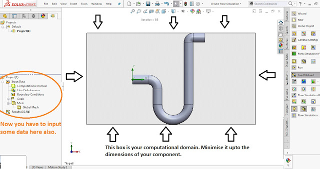
The box appearing around the body is your computational domain (the volume in which flow will occur). Minimise this box upto the size of the body. In the input data menu you have
Step 3 b:
the click right there here red arrow is pointing ie. project , then left click and run the study.
Step 3 c:
It will take a couple of second or minute to finish after it the results will be loaded and you can choose type of result you want.
I selected flow trajectories for my analysis.
Step 4: in flow trajectories: You have to choose
Starting point by means of
Now your work is done and play the trajectories and watch them.
Videos of simulation: video link 1 video link 2
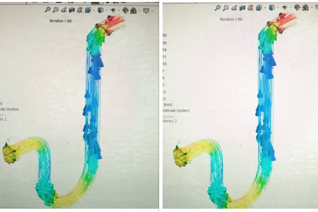
Images of simulation: image 1 image 2 image 3
Moreover we can further have more applications of CFD which i was not able to explain through this tutorial .
Electronics Cooling Module
Electronics Cooling Module (ECM) provides additional materials and material models that are specific to circuit board and PCB enclosure analysis. The Two-Resistor component model is a JEDEC approved method for simulating chip temperature such as BGA, QFP, QFN and SOP. The PCB-generator understands layer properties to provide an accurate orthotropic thermal behavior. Joule heating capabilities mean designers can apply current as the input to estimate heat generation.
Free Surface Dynamics
Free surface is a condition with a freely moving surface between two fluids that don’t mix such as
air and water. Using the Volume of Fluids approach, we can accurately simulate transient conditions
such as tank sloshing or any open bath fluid behavior. Not only can these test give us a better
understanding of what the fluid is actually doing in the system, but we can also gather useful
quantitative results such as force or pressure on internal walls.
HVAC Module
Accurately understanding HVAC systems is a complicated task. That’s why SOLIDWORKS created the HVAC add-on module for SOLIDWORKS Flow Simulation. This tool provides additional capabilities such as advanced radiation which modifies the way radiation between bodies, including semi-transparent materials such as glass, is calculated to provide higher fidelity of result information. The tracer study function allows the simulation of pollutants in a volume and shows how and where that pollutant will disperse in an environment.
Share your experiences of flow simulation here and try to help beginners who need it.
Simulation is simply how a product or a part behaves under some fixed condition for ex if i push a square block with some force how the block behaves or changes its dimension (minimal) under that force, or suppose the door of your room is blocked and you are trying to open it by pushing it so how the door is going to behave and how much force you need to apply to open that one is given by simulation.
Simulation is also used when the real system cannot be engaged, because it may not be accessible, or it may be dangerous or unacceptable to engage, or it is being designed but not yet built, or it may simply not exist. ex you have to design a car for your customers ,you can't just start manufacturing it by welding ,joining ,cutting .You have to make a prototype (model) on cad softwares ,analyse its working ,test it on different parameter and after you are all done with your model then start manufacturing.
In flow simulation we analyze the flow of fluids over a body or from inside/through a body .Its application are designing of airplane, cars,vents, heat transfer and many more. It can be used in many industries including aerospace, power generation, oil & gas power conversion, transportation, additive manufacturing, automotive, and others. CFD capabilities cover a wide range of application within these industries including turbomachinery rotating cavity systems, secondary flow & engine sealing, combustor cooling, fuel/lube systems, and power plant piping networks. it can also be used for renewable wind turbines and electrical generator cooling and thermal management. For additive manufacturing, it allows for heat exchanger design and optimization.
SOLIDWORKS Flow Simulation is a general parametric flow simulation tool that uses the Finite Volume Method (FVM) to calculate product performance through “what if” studies that allow you to perform optimization using the results.
Solidworks Flow Simulation
Here i am using solidworks flow simulation to show you how to analyze the flow through a body.Step 1:
Make your part/component over which analysis is needed and save it. I created a hollow U tube .Add flow simulation add ins from the options in menu bar. If it is already there in your command manager then you can proceed to step 2.
Step 2 a:
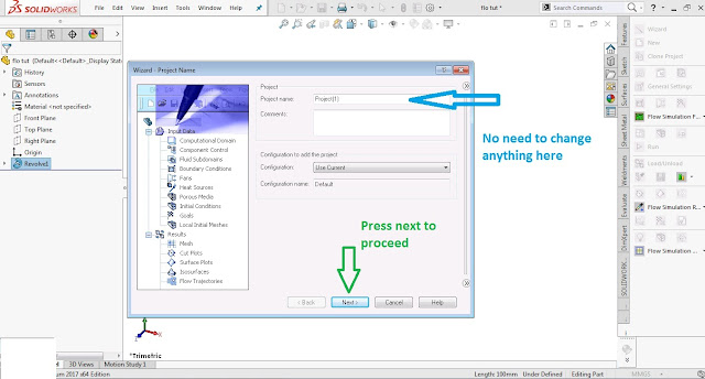
Click the first option Wizard in command manager. then a new window will open which will ask you to input various things/conditions .
In the below shown window you can edit your project name or just leave it, and then click next.
Step 2 b:
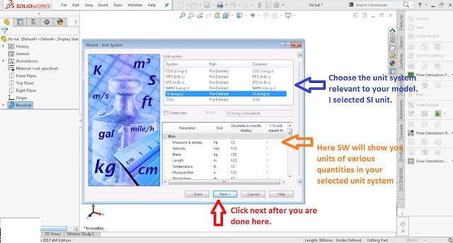
In the below shown window choose your unit system .Prefer SI unit system and in tab below to this it will show you unit of various quantities in that unit system . After you are done click next.
Step 2 c:
In next window you have to choose type of analysis.
- Internal analysis -done inside a compartment or it is confined in a chamber . ex flow of air in a closed room ,heat flow through fans ,heat exchanger ,heat flow in IC's(Integrated circuit), PCB enclosures, valves, pumps and manifolds are all examples of internal analysis studies. setting up computational domains, boundary conditions and heat sources can be done in minutes. The results of your analysis can be applied directly to your design allowing you to test more iterations in less time.
- External analysis -done over a body or part. flow over cars ,flow over airplanes, flow through turbines and pumps External analysis is used when we need to understand the fluid behavior around our model based on the environment conditions. Wind Turbines, Airplanes, ships, heat sinks, and automobiles would all be studied using external flow analysis. In External studies, the computational domain acts as our virtual wind tunnel with boundary conditions, heat sources.
For my present body i used External analysis.
In physical features menu there are
- Heat conduction in solid-select it when there is some sort of heat exchange in your component.
- Radiation-select it when there is heat flow through radiation.
- Time dependent-I don't know about it as i never used it.
- Gravity-choose it every time as Gravity is present everywhere .You can manipulate its value.
- Rotation-applicable in case of turbine ,pumps etc.
Coming up with optimal designs for systems with fan blades or impellers is impossible without
accurate results.Flow Simulation provides users with tools that allow for rotating regions and sliding mesh methods to accurately simulate the behavior of these types of systems based on geometry, angular velocity, and transient behavior of the fluid.

Step 2 d:
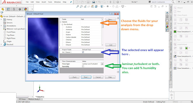
Choose the type of fluid for your CFD/Flow analysis .There are hundreds of fluid available here. From newtonian to ideal ,from real gases to liquid and still many more..
In Flow type you can enter the flow you desire.Laminar ,turbulent or both. You can leave it as default also.
Step 2 e:
In this window you can add wall roughness factor and thermal conditions. For my analysis i leave it as it is.
Step 2 f:
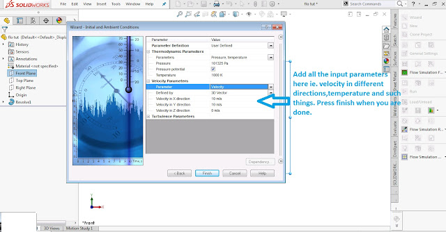
Here input the thermodynamic and velocity parameters .
Thermodynamic parameters- add pressure ,temperature etc.
Velocity parameters- add velocity in terms of mach number or absolute numbers in X ,Y ,Z directions.
After it click finish.
Step 3 a:
The box appearing around the body is your computational domain (the volume in which flow will occur). Minimise this box upto the size of the body. In the input data menu you have
- Computational domain- you can adjust it as per needs.
- Fluid subdomains- can be ignored.
- Boundary conditions- use it for constraining inlet mass flow ,inlet velocity ,inlet mach number etc and apply them over a face of body.
- Goals* -This is most important part . Choose global goals then choose all those things from checkboxes which you want to calculate or analyse .ex pressure ,temperature ,mach no, viscosity etc.
- Mesh- in this you can divide/adjust the size of the cells of domain or leave it to default.
Now you have to run the study.
Step 3 b:
the click right there here red arrow is pointing ie. project , then left click and run the study.
Step 3 c:
It will take a couple of second or minute to finish after it the results will be loaded and you can choose type of result you want.
I selected flow trajectories for my analysis.
Step 4: in flow trajectories: You have to choose
Starting point by means of
- pattern :planes
- pick from screen : choose starting point
- coordinates: X Y coordinates by giving input .
- bands
- spheres
- arrows
Now your work is done and play the trajectories and watch them.
Videos of simulation: video link 1 video link 2
Images of simulation: image 1 image 2 image 3
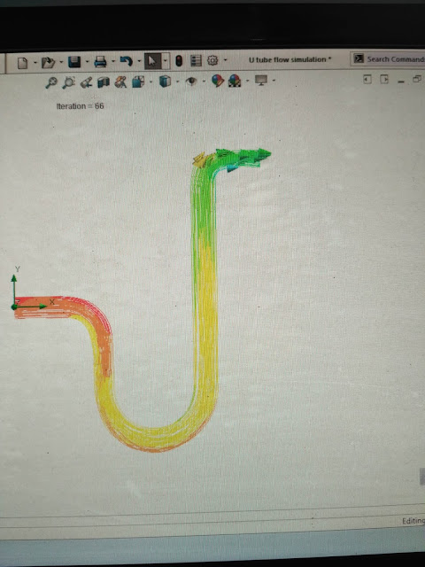 |
| These colorful arrows are streamlines showing fluid flow |
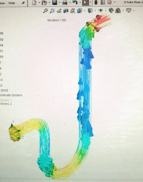 |
| These colorful arrows are streamlines showing fluid flow |
 |
| These colorful arrows are streamlines showing fluid flow |
Moreover we can further have more applications of CFD which i was not able to explain through this tutorial .
Electronics Cooling Module
Electronics Cooling Module (ECM) provides additional materials and material models that are specific to circuit board and PCB enclosure analysis. The Two-Resistor component model is a JEDEC approved method for simulating chip temperature such as BGA, QFP, QFN and SOP. The PCB-generator understands layer properties to provide an accurate orthotropic thermal behavior. Joule heating capabilities mean designers can apply current as the input to estimate heat generation.
Free Surface Dynamics
Free surface is a condition with a freely moving surface between two fluids that don’t mix such as
air and water. Using the Volume of Fluids approach, we can accurately simulate transient conditions
such as tank sloshing or any open bath fluid behavior. Not only can these test give us a better
understanding of what the fluid is actually doing in the system, but we can also gather useful
quantitative results such as force or pressure on internal walls.
HVAC Module
Accurately understanding HVAC systems is a complicated task. That’s why SOLIDWORKS created the HVAC add-on module for SOLIDWORKS Flow Simulation. This tool provides additional capabilities such as advanced radiation which modifies the way radiation between bodies, including semi-transparent materials such as glass, is calculated to provide higher fidelity of result information. The tracer study function allows the simulation of pollutants in a volume and shows how and where that pollutant will disperse in an environment.
Share your experiences of flow simulation here and try to help beginners who need it.
Thanks for reading it till now :D
Stay tuned for further updates...





Content was very helpful
ReplyDeleteVery useful
ReplyDelete