Posts

Showing posts from March, 2020

Notches and Weirs- Their classification and types

Image
Notch- is a device used for measuring the rate of flow or discharge of a liquid through  small channel or tank. Weir- is a concrete or masonry structure, placed in an open channel over which the flow occurs. It is form of vertical wall , with the sharp edge at the top, running all the way across the open channel. Notches Weirs 1. A notch may be defined as an opening provided in one side of a tank or reservoir,with upstream liquid level below the top edge of opening. 1. A weir may be defined as a structure constructed across a river or canal to store water on the upstream side. 2. The sheet of water flowing through a notch is called Nappe.  2. The sheet of water flowing over a weir is called Vein.  3. The bottom edge of a notch is called Crest. 3. The bottom edge of a weir is called Sill. 4. Usually made of metallic plates.  4. Weir is a concrete or masonry structure 5. Measures small discharge of small stream, lake or canal. 5. It can measure large disch

Hydraulic Machines -Turbines, and its Classification

Image
Turbines are defined as the hydraulic machines which convert hydraulic energy into mechanical energy . This mechanical energy is used in running an electric generator which is directly coupled to the shaft of turbine. Thus the mechanical energy is converted into electrical energy . The electric power which is obtained from the hydraulic energy (Energy of water) is known as Hydroelectric power . At present the generation of hydroelectric power is the cheapest as compared by the power generated by other source such a oil,coal etc. Some Facts about the present day water turbines Johann Segner developed a reactive water turbine (Segner wheel) in the mid-18th century. In 1820, Jean-Victor Poncelet developed an inward-flow turbine. In 1826, Benoit Fourneyron developed an outward-flow turbine. This was an efficient machine (~80%) that sent water through a runner with blades curved in one dimension. The stationary outlet also had curved guides. In 1849, James B. Francis improved

Numericals on Klein's Construction

Image
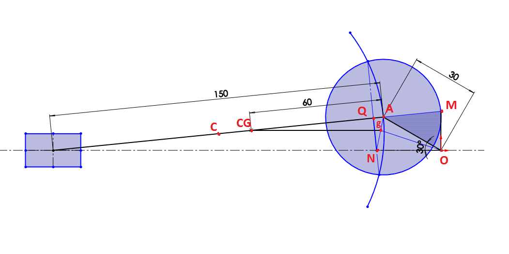
Hello everyone , today i am going to solve some numericals on Klein's Construction. Previously i have explained you how to apply this method on single slider crank mechanism. If you are first time here then i insist you to view the first part on this topic here :  farooq blogs kleins construction In first numerical there is center of gravity of connecting rod given and we have to calculate the angular acceleration of CG of connecting rod. In second numerical the crank length and connecting rod are given in the form of stroke and obliquity ratio , first we have to calculate length of crank and connecting rod . Ques 1 . Determine the velocity and acceleration of each link in a single slider crank mechanism by using Klein's Construction method .Also determine the acceleration of center of gravity of connecting rod. Crank length= 90 mm Connecting Rod length= 450 mm Crank angle from IDC= 30 deg. Center of gravity of connecting rod from crankpin= 180 mm Speed N=600 rpm in C

Klein's Construction

Image
Klein's Construction - is an graphical method to find velocity and acceleration of reciprocating parts of steam engine or internal combustion engine . In Klein's Construction the velocity and acceleration diagrams are made on configuration diagram itself. The line that represents the crank in the configuration diagram also represents the velocity and acceleration of its moving end in the velocity and acceleration diagrams respectively. By using this method we can find the velocity and acceleration of crank,connecting rod ,piston. Klein's Construction This method is applicable only if α of crank=0 or ω of crank=constant Method of obtaining velocity and acceleration  from the given values of crank length(r) and its angular velocity(ω) calculate crank velocity by  crank velocity Vc=r*ω crank acceleration Ac=r*ω*ω if dimensions of crank and connecting rod are such that they can be drawn on paper then there is no need to scale down the dimenions. if