Hydraulic Machines -Turbines, and its Classification
Turbines are defined as the hydraulic machines which convert hydraulic energy into mechanical energy. This mechanical energy is used in running an electric generator which is directly coupled to the shaft of turbine. Thus the mechanical energy is converted into electrical energy.
The electric power which is obtained from the hydraulic energy (Energy of water) is known as Hydroelectric power. At present the generation of hydroelectric power is the cheapest as compared by the power generated by other source such a oil,coal etc.
The specific speed is used in comparing the different types of turbines as every type of turbine has different specific speed.
Specific speed for Pelton turbine ranges between 8.5 to 30 (with single jet)
Specific speed for Francis turbine ranges between 51 to 225
Specific speed for Kaplan turbine ranges between 255 to 860
a general equation for specific speed is given by
Ns= specific speed of a turbine
N=speed of actual turbine
P=Power developed or shaft power
H=Head under which turbine is working
Difference between impulse turbine and reaction turbine
The electric power which is obtained from the hydraulic energy (Energy of water) is known as Hydroelectric power. At present the generation of hydroelectric power is the cheapest as compared by the power generated by other source such a oil,coal etc.
Some Facts about the present day water turbines
- Johann Segner developed a reactive water turbine (Segner wheel) in the mid-18th century.
- In 1820, Jean-Victor Poncelet developed an inward-flow turbine.
- In 1826, Benoit Fourneyron developed an outward-flow turbine. This was an efficient machine (~80%) that sent water through a runner with blades curved in one dimension. The stationary outlet also had curved guides.
- In 1849, James B. Francis improved the inward flow reaction turbine to over 90% efficiency. He also conducted sophisticated tests and developed engineering methods for water turbine design. The Francis turbine, named for him, is the first modern water turbine. It is still the most widely used water turbine in the world today. The Francis turbine is also called a radial flow turbine, since water flows from the outer circumference towards the center of runner.
- A Pelton wheel is an impulse-type water turbine invented by Lester Allan Pelton in the 1870.
- Around 1913, Viktor Kaplan created the Kaplan turbine, a propeller-type machine. It was an evolution of the Francis turbine and revolutionized the ability to develop low-head hydro sites.
General Layout of a Hydroelectric Power Plant
Working principle of Hydraulic Turbines
They work on Newton second law of motion which states that force is directly proportional to rate of change of momentum. When the rapidly flowing water strikes the blades of turbine there is an change of momentum of water which produces a force on the blades, the blades start moving and hence the turbine rotates. The shaft of turbine is coupled to a generator and in this way electrical energy is produced.
Definitions of Head and Efficiencies of a Turbine
1. Gross Head : The difference between the head race level and tail race level when no water is flowing is known as gross head. It is denoted by 'Hg'.
2. Net Head : also called effective head as the head available at the inlet of the turbine. When water i flowing from the head race to the turbine , a loss of head due to friction between the water and penstock occurs. Though there are other losses such as loss due to bend , pipe fittings , losses at entrance and exit of penstock etc.,yet they are having small magnitude as compared to head loss due to friction. If 'hf' is the head loss due to friction then net head on turbine is given as :
H= Hg - hf
where Hg =Gross Head
and hf= (4*f*L*V^2) /(2*g*D)
where
V=velocity of flow in penstock
L=length of penstock
D=diameter of penstock
3. Efficiencies of a Turbine :There are 4 important efficiencies of a turbine
a) Hydraulic Efficiency η(h) : ratio of power delivered to runner to the power supplied by the water at inlet of turbine.
η(h)=power delivered to runner / power supplied by the water
η(h)= Runner Power / Water Power
- Power supplied at the inlet of turbine in SI units is known as Water Power (WP)
WP= (ρ*Q*g*H) / 1000 in Kilo Watt
b) Mechanical Efficiency η(m): ratio of power available at the shaft of turbine to the power delivered to the runner
η(m)= Power at the Shaft of turbine / Power delivered by water to Runner
or η(m)= Shaft Power / Runner Power
c) Overall Efficiency η(o) : ratio of power available at the shaft of turbine to the power supplied by the water at inlet of turbine.
η(o)= Shaft Power / Water Power
multiplying numerator and denominator by Runner Power and then rearranging you get
η(o)= (Shaft Power / Runner Power) * (Runner Power / Water Power)
⇒η(o)= η(m) * η(h)
Classification of Hydraulic Turbines
Hydraulic Turbines are classified according to energy available at inlet of the turbine, direction of flow through the vanes , head available at the inlet of turbine and specific speed of the turbines. Thus following are the important classification:
1. According to the energy available at inlet
a) Impulse turbine b) Reaction turbine
2. According to the direction of flow through runner
a) Tangential flow turbine b) Radial flow turbine c) Axial flow turbine d)Mixed flow turbine
3. According to the head available at the inlet
a) High head turbine b) Medium Head turbine c) Low head turbine
4. According to the specific speed of the turbines
a) Low specific speed turbine b) Medium specific speed turbine c) High specific speed turbine
Impulse Turbine- If at the inlet of the turbine, the energy available is only kinetic energy, the turbine is known as Impulse turbine. ex. Pelton turbine.
Reaction Turbine- If at the inlet of the turbine, the water possesses kinetic energy as well as pressure energy, the turbine is known as Reaction turbine. ex francis, propeller, kaplan turbine are reaction turbines.
ex. Pelton turbine in which jet strikes pelton bucket tangentially.
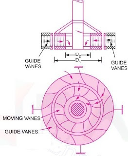
Radial flow turbine- If the water flows in the radial direction through the runner, the turbine is called radial flow turbine.
If the water flows from outside to inward, radially ,the turbine is known as inward radial flow turbine, on the other hand ,if the water flows from inward to outward the turbine is known as outward radial flow turbine.
Axial flow turbine- water flows through the runner along the direction parallel to the axis of rotation of runner.

Mixed flow turbine- water flows through the runner in the radial direction but leave in the direction parallel to the axis of rotation of runner, the turbine is Mixed flow turbine.
Impulse Turbine- If at the inlet of the turbine, the energy available is only kinetic energy, the turbine is known as Impulse turbine. ex. Pelton turbine.
Reaction Turbine- If at the inlet of the turbine, the water possesses kinetic energy as well as pressure energy, the turbine is known as Reaction turbine. ex francis, propeller, kaplan turbine are reaction turbines.
- There is a very big myth that Impulse Turbine is somewhat related to Impulse but the fact is there is no such thing. The same is also in case of Reaction Turbine
- A the water flows through the runner, the water is under pressure and the pressure energy goes on changing into kinetic energy.
- The runner is completely enclosed in an air-tight casing and the runner and casing is full of water.
ex. Pelton turbine in which jet strikes pelton bucket tangentially.
watch the full Pelton turbine working animation on my Youtube channel here: Pelton Turbine
Radial flow turbine- If the water flows in the radial direction through the runner, the turbine is called radial flow turbine.
If the water flows from outside to inward, radially ,the turbine is known as inward radial flow turbine, on the other hand ,if the water flows from inward to outward the turbine is known as outward radial flow turbine.
Axial flow turbine- water flows through the runner along the direction parallel to the axis of rotation of runner.

Mixed flow turbine- water flows through the runner in the radial direction but leave in the direction parallel to the axis of rotation of runner, the turbine is Mixed flow turbine.
A comparison of all types of flow
Classification based on specific speed of the turbines
Specific speed is defined as speed of turbine which is identical in shape, geometrical dimensions etc. with the actual turbine but of such size that it will develop unit power when working under unit head.The specific speed is used in comparing the different types of turbines as every type of turbine has different specific speed.
Specific speed for Pelton turbine ranges between 8.5 to 30 (with single jet)
Specific speed for Francis turbine ranges between 51 to 225
Specific speed for Kaplan turbine ranges between 255 to 860
a general equation for specific speed is given by
Ns= specific speed of a turbine
N=speed of actual turbine
P=Power developed or shaft power
H=Head under which turbine is working
Difference between impulse turbine and reaction turbine
Advantages of Hydraulic turbines
1. It is an renewable energy source. The water energy can be used again and again.
2. Negligible environmental pollution.
3. Low running cost.
4. Easy to maintain.
5.These turbines have higher efficiency.
1. It is an renewable energy source. The water energy can be used again and again.
2. Negligible environmental pollution.
3. Low running cost.
4. Easy to maintain.
5.These turbines have higher efficiency.
Disadvantages of Hydraulic turbines
1. Very high installation cost. The plant takes several decades to produce profit.
2. The plant can be developed only at few sites where proper amount of water is present.
view my articles on klein's construction here :Kleins Construction
view my articles on klein's construction here :Kleins Construction
Thanks for reading till now
Stay tuned...
:)


Comments
Post a Comment